The Shunt Reactor Loss Measurement system is a microprocessor-controlled, metrology-based, high-voltage capacitance, inductance and reactor loss measurement bridge which is based on the two-stage-compensated current transformer. The 7010C bridge can be ordered by itself or it can be ordered with high-voltage capacitors up to 800 kV line-to-ground and two-stage-compensated current transformers up to 4000 A. The system is fully automatic displaying the RMS voltage at the top of the capacitor, the reactor current and the reactor losses.
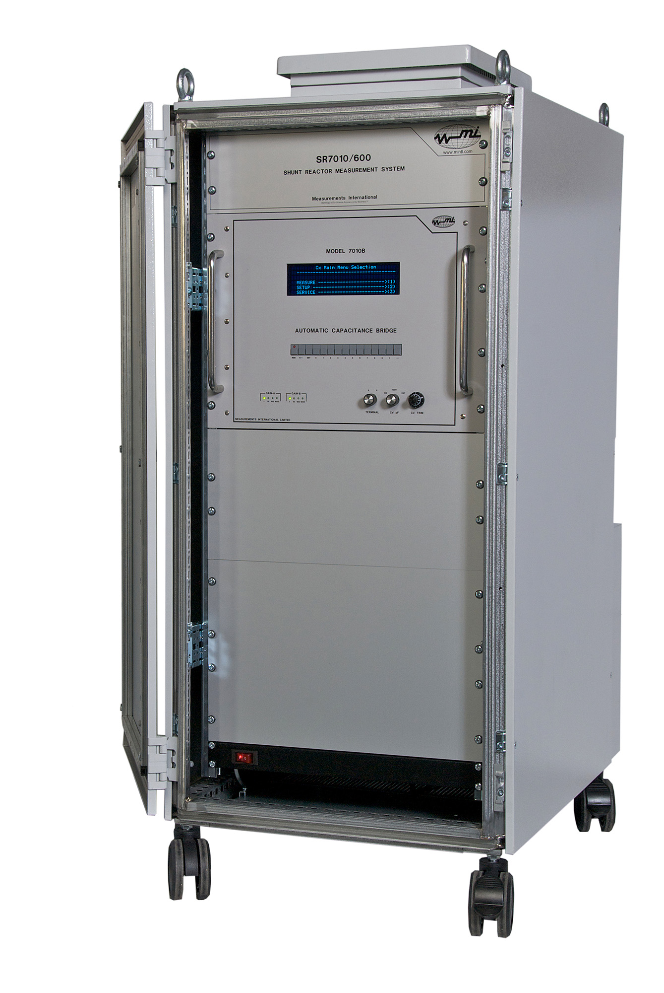
The Acculoss® Shunt Reactor Loss Measurement System is a complete loss measurement system designed for power frequency testing and calibration of medium and large power shunt reactors. The measurement capability of the model SR 7010/400 is 400 kV (line-to-ground) and currents up to 4000 A at frequencies of 50/60 Hz. A large 7″ (178.5 mm) touch screen display, located on the front panel, is used to enter data and configure the input of the 7010C.
The USB slot on the front panel is used to save measurement setups and measurement data. The easy to use touch screen menus allow the operator to select the number of readings for statistical analysis of the uncertainty calculations at the 95 % (2 s) level. Measurement parameters for capacitance and inductance can be transmitted over the IEEE-488 interface for storage to a computer.
The automatic self-balancing feature facilitates the use of the bridge for accurate load loss measurements of large high-voltage inductive loads. Touch screen menus allow the operator to select capacitance, inductance and reactor loss measurement functions.
The model 7010C is a capacitance/inductance bridge with a maximum ratio of 1000:1 making it ideal for both low- and high-voltage applications. Overall accuracy is < 15 ppm in magnitude and phase. The 7010C has ratios of 1, 2, 5, 10, 20, 50, 100, 200, 500 and 1000:1 and dissipation (loss tangent) measurements from 0 to 10 % with a resolution of 1 ppm.
To accommodate larger capacitance ratios than 1000:1 an additional two-stage range extender, model 7020 may be added to increase the ratio to 2,000,000:1. All connections are made on the rear of the 7010C bridge. The current input is secured using a locking connector and the voltage input is secured by a BNC locking connector. It also has a schematic for measuring losses with the 7020-2000:1 range extender and the high-voltage capacitor. Leads up to 50 metres are available for connecting the output of the high-voltage capacitor and model 7020 range extender.
RLMS2400
(2000 A, Ratio 2,000,000:1, 400 kV L-G)
RLMS2600
(2000 A, Ratio 2,000,000:1, 600 kV L-G)
RLMS2800
(2000 A, Ratio 2,000,000:1, 800 kV L-G)
Optional Shielded Rack
The 7010C can be supplied as a laboratory benchtop instrument or a test floor unit on castors for portability allowing the user to move it about the test floor. All inputs are located on the rear of the rack. Locking BNC connectors are used to connect the high-voltage capacitors. Two current inputs are provided. The current input of the 7010C has both a locking connector on the output of the 7020 Range Extender and a locking connector on the input of the 7010C as well as a five-way binding post input for connecting other manufacturers current transformers.
Optional High-Voltage Capacitors – CG Series
The high-voltage capacitors consist of a low-voltage measurement electrode which is isolated from the high-voltage electrode by a dielectric gas (SF⁶). A guard electrode or grounding technique can be used to eliminate parasitic capacitance. Grounding or connecting the guard circuit is specific to the installation and application.
| CG 100 – 100 pF 100 kV | – Voltage range: 50 kV to 500 kV | |
| CG 200 – 100 pF 200 kV | – Tangent delta (Tan ẟ): < 1.10-5 | |
| CG 300 – 100 pF 300 kV | – Nominal capacitance: 5 pF to 1000 pF | |
| CG 400 – 100 pF 400 kV | – Voltage coefficient: < 30 ppm (Typically < 10 ppm) | |
| CG 500 – 100 pF 500 kV | – Stability / year: < 0.05 % |
Note: For higher voltages please contact MI
Note: 50 pf Capacitors also available
| Capacitance Range | Cs: 10 pF to 10,000 pF Cx: 10 pF to 10,000,000 pF (10 µF) |
| Capacitive Ratio 1:1 to 1000:1 | Ns: 0 to 1.11110 in steps of 0.000001 Nx: 1 to 1000 in steps of 1, 2, 5 |
| Primary Current | 10 Amp Maximum |
| Secondary (Cs) Current Range | 40 µA to 10 mA |
| Dissipation Factor Range | 0 to 10 % in steps of 0.000001 |
| Inductance Range | 700 µH to 700000 H (Q factor > 10) |
| Test Frequencies | 50 and 60 Hz |
| Accuracy | Ratio: ± 15 ppm for all Cx Ratios |
| Loss Angle | ± 1 % of Reading ± 10 ppm |
| Display | 7-inch Screen Display |
| Warm-Up Time | < 5 Minutes to Full Rated Accuracy |
| Operating Environment | 18 to 34 °C, 10 to 80 % RH |
| Operating Power | 100, 120, 220, 240 V – 50/60 Hz |