The measurement of electric power and energy at high-voltages and currents at low power factors is becoming increasingly important economically as a way to reduce costs in an ever-growing industrial economy. Today the transformer purchaser subjects the transformer manufacturer to an economic penalty for losses that occur in load and no-load conditions. To keep these penalties as low as possible, it is important that the manufacturer accurately measure these losses. Failure to do so can result in the manufacturer losing important contract awards to their competitors who may be utilizing a more accurate system.
Using “State-of-the-Art” proven two-stage-current comparator technology, the AccuLoss® series of Transformer Loss Measurement Systems is designed to meet the needs of today’s transformer manufacturer by providing the most accurate power loss measurement system in the world. Designed for power frequency testing and calibration, the AccuLoss® system can be used for testing small, medium and large power transformers as well as motors and turbines up to 400 Hz. The system is also ideal for R & D facilities and can also be used to measure losses in single and three-phase reactors.
The AccuLoss® series of Transformer Loss Measurement Systems has been accepted and installed by transformer manufacturers around the world and distinguished itself in the rugged transformer manufacturing environment. There are two types of bushings available for the AccuLoss® system, Vertical Loss Measurement System for systems above 58 kV L-N and Horizontal for systems below 58 kV L-N.
The AccuLoss® system includes a powerful “operator friendly” software. Included are voltage and current waveform analysis, manual and fully automatic time-saving range selection and over voltage and over current protection.
The AccuLoss® system controller can be directly connected to the plant LAN for transferring data to a host computer for backup and further processing including generating customer reports. As an option, AccuLoss® can be controlled remotely from a separate program running on another computer. This is very helpful in those situations when AccuLoss® has to be controlled automatically and from a different location.
The AccuLoss® system is a complete transformer loss measuring system and is in compliance with the latest standards and specifications dealing with the calibration of test systems to measure transformer losses.
Capabilities
AccuLoss® Features
Benefits
System Measurements
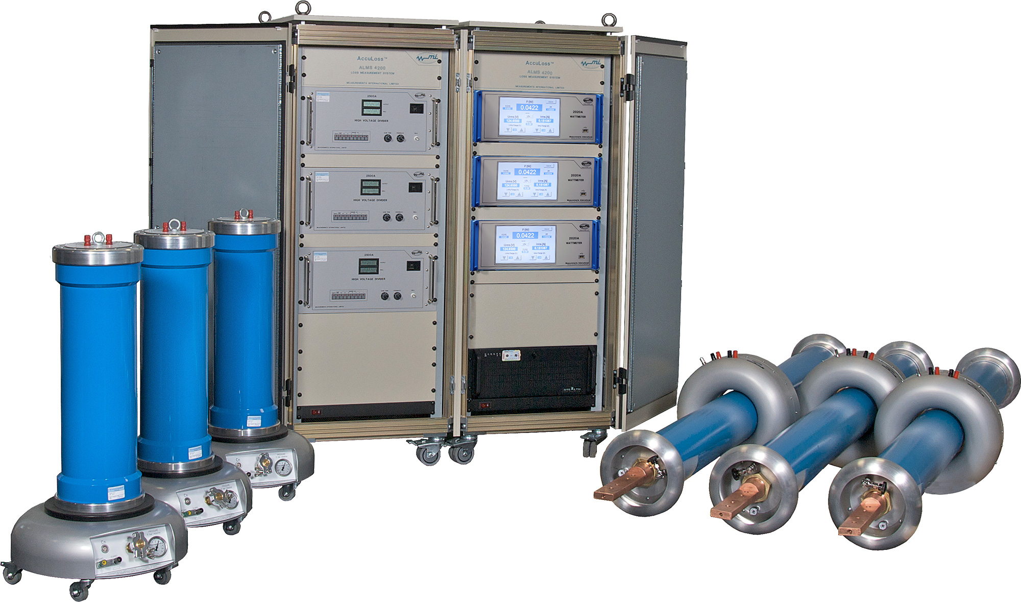
Voltage Arm: A capacitive divider consisting of three (3) shielded gas-filled (SF6) high-voltage standard capacitors and three model 2500A Voltage Dividers are used for measuring the phase-to-ground voltage in each phase. The output of the high-voltage standard capacitor is connected to the voltage input of the instrument rack and then directly into the voltage input of the model 2500A Voltage Divider.
In the ALMS 2058 (2000 A) the model 7020H Precision Current Transformer has only one range of 1000:1. In the model ALMS 4058 (4000 A) the range is 2000:1. The linearity of the two-stage compensated current transformer is less than a few ppm, so measurements as low as one Ampere (100 mA) can be made with ease in the ALMS 2058. Subsequent current ranging is provided in the 2020A Power Analyzer which has 10 current ranges in stages of 5, 2, 1, 0.5, 0.2, 0.1, 0.05, 0.02, 0.01 and 0.005 A.
The model 2020A Power Analyzer uses a multi tapped two-stage-compensated CT to perform the switching on its input to measure the current. The current value is displayed on the power analyzer and the control screen. The two-stage-compensated CT within the power analyzer reduces the error of the High-Voltage Current Transformer to a few ppm in magnitude and phase.
Power Measurement
The model 2020A Power Analyzer displays the power of all three phases at the input to the power analyzer. The sum of the three phases is calculated and displayed on the controller screen. Automatic ranging of the model 2500A High-Voltage Dividers and the model 2020A Power Analyzer ensures that each component measures in the best range. The values are calculated and displayed with 5-digit numbers on the screen.
Accuracy and Uncertainty: The maximum power measurement accuracy and uncertainty of the AccuLoss® series of loss measurement systems are shown below as a function of the power factor. This accuracy can further be improved by asking for a National Measurement Institute (NMI) calibration of the components. An optional system calibration is also available.
The AccuLoss® series of Loss Measurement Systems utilizes the globally recognized LabVIEW™ interface from National Instruments. The software runs in a Windows® operating environment and is fast, easy and intuitive. Large buttons on the main screen are used to ensure correct settings for the measurements. All measurement data is displayed on the measurement screen as well as waveforms for the three voltage and three current channels. Measurement data is stored in an ASCII file which can be exported over the ethernet to the main computer for analyzing and producing calibration reports.
The software can be modified to meet the specific needs of the user prior to shipment of the system.
Main Screen: The Main screen provides easily recognized icons for entry into the UUT Data, Test GPIB and Calibration data entry screens. Test configuration selectors are also available.
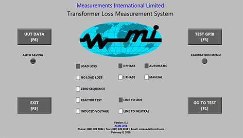
Main Menu Screen
The Main Menu Screen is divided into four (4) sections:
The Measurement Screen allows the operator to quickly review the measurement data. Included on this screen is the Hold [F6] and Save button for saving the data to an ASCII file. The Hold and Save button toggle back and forth depending on which is selected. Each phase is distinguished by different colours making the screen data easier to view and monitor. Large green displays are used to display the combined power, voltage and current. The large screens can also be used to monitor the generator voltage adjustments.
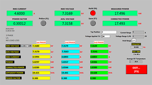
Measurement Screen
Scrolling down to the bottom of the screen reveals the Waveform Analyzer showing the waveforms for both current and voltage on all three phases including even and odd harmonics up to the 25th harmonic. These waveforms can also be printed at the time of measurement.
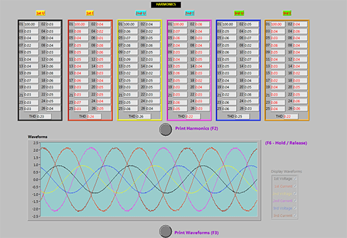
Waveform Analyzer Screen
The Measurement Screen displays are updated every second. The controller reads each power analyzer and displays the input voltage and current and calculates the real power, the apparent power and the power factor.
Hardware
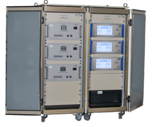
Control Cabinet: The control cabinet houses the electronics and is protected against impulse through the input and ground connections.
The model 2500A Voltage Dividers, model 2020A Power Analyzers, a Line-to-Line buffer and Industrial Grade PC Controller are housed in the cabinet. The three current transformer and three high-voltage capacitor connections are made at the rear of the control cabinet. A printer, keyboard and monitor port is also available on the rear panel.
| Model | ALMS 1058 & ALMS 2058 | ALMS 4058 |
| Voltage(1) | ||
| Applied Voltage | 100 V to 58 kV Line-to-Line | 100 V to 58 kV Line-to-Line |
| Accuracy | 0.05 % | 0.05 % |
| Ranges | 1 kV, 2 kV, 5 kV, 10 kV, 20 kV, 50 kV, 100 kV | 1 kV, 2 kV, 5 kV, 10 kV, 20 kV, 50 kV, 100 kV |
| Current(2) | ||
| Applied Current | 1 A to 2000 A (1000:1 ratio) | 1 A to 4000 A (2000:1 ratio) |
| Accuracy | 0.05 % | 0.05 % |
| Ranges ALMS 1058 | 5 A, 10 A, 20 A, 50 A, 100 A, 200 A, 500 A, 1000 A | 10 A, 20 A, 40 A, 100 A, 200 A, 400 A, 1000 A, 2000 A, 4000 A |
| Ranges ALMS 2058 | 5 A, 10 A, 20 A, 50 A, 100 A, 200 A, 500 A, 1000 A, 2000 A | |
| Safety Clearances | ||
| To Adjacent Walls | 1 metre | 1 metre |
| Between Phase | 1.73 metres | 1.73 metres |
| Power Supply | ||
| Voltage | 100, 120, 220, 240 ± 10 % | |
| Frequency | 50/60 Hz | |
| Power | 1200 VA | |
| Environmental Conditions | ||
| Operating Temperature | Control Cabinet: 15 to 30 °C, Bushings and Capacitors: -10 to 40 °C | |
| Storage Temperature | -20 to 50 °C | |
| Relative Humidity | 30 to 90 % (non-condensing) | |
| Statement of Standard Deviation | 2 Sigma | |
(1) 10 to 110 % range utilization, includes uncertainty of calibration
(2) Current measurement has 50 % overrange capability, minimum current is 100 mA with 100 mA option